author: Jonathan Filippi
Read before building:
This device produces high voltage pulses disrupting muscles and nervous system, leaving anyone who touches it in a state of mental confusion. Can be used again ferocious animals or attackers, BUT REMEMBER, this device may be illegal in your state (for eg where I live, these devices are banned). It is quite dangerous for peoples experiencing cardiac problems, and for electronic equipment (like peacemakers), since it generates some RF. Don't attempt irresponsible actions with this device, it is not a toy.
After the introduction let's pass to the circuit.
The 555 IC is wired as a astable to produce square wave with adjustable freq and duty cycle (notice the potentiometers and diode). This square wave is feed to a IRF840 Mosfet (no need of totem transistors since freq is low and the IC has enough current capability to rapidly charge/discharge the gate). As a substitute of the mosfet, a bipolar transistor can be used (and a 100ohm resistor between 555 and base of the transistor). Valid BJT can be BU406, but also smaller BJT can be OK, keep in mind that it must handle at least 2A continuous. The inductive kick snubber isn't needed because the power is low and it is almost totally adsorbed to charge the tank capacitor, in addition since this device is battery operated we don't want to dissipate the power on a resistor but we want it in sparks. With a snubbing network you will experience lower firing rates. USE A PUSHBUTTON SWITCH FOR SAFETY
Construction of T2: this is the real boring part. Since it is unlikely to find it in shops we need to build them. Materials needed: enamel copper wire (0,20 mm or 0,125 mm), ferrite stick, LDPE sheets (0,25 mm). Secure the ferrite stick with a layer of ldpe (polyethilene, as a substitute use electric insulating tape) and glue it (or tape it) Place 200-250 windings on the ldpe (even more windings if the stick is more than 1'), another ldpe layer, another 200-250 windings and so on to finally have 5-6 layers (approx 1000-1400 turns but even more doesn't hurt performance, but be careful for internal arcing that will ruin it). Insulate it again and place the primary winding, 15-20 turns of 1mm wire are just ok, too much windings (too mush resistance and inductance) will lead to smaller current and smaller spike in T2 secondary because of lower rise time,and too few will not saturate the core. I chosen MKP capacitors because they have low ESR and ESL (they are widely used in tesla coils as mmc capacitors).
The spark gap can be simple two crossed (but not touching) 1 mm spaced wires. It acts as a voltage controlled switch, firing when
the voltage is enough to ionize the air between them (turning it to plasma with small resistance). Keep in mind that it would
be wise do place it into a small plastic container and fill with oil letting bubbles out (don't use motor oir or frying oil
but pure mineral oil which has no water in it.
Disclaimer: As i have seen before, IT IS NOT A TOY, DON'T DO ANYTHING STUPID WITH IT. I DON'T ACCEPT ANY RESPONSIBILITY OF DAMAGES DONE TO OTHER PEOPLE OR YOURSELF WITH THIS DEVICE. IF YOU WANT TO BUILD IT YOU MUST ACCEPT THIS CONDITION. Using the procedures described above would prevent you from any damages/troubles. Don't carry it in streets or public places if they are banned in your country, and don't use it near electronic devices. As the wise man says use it like a deterrent, even against animals.
from http://www.electronics-lab.com

Basic UPS Power Supply
source: Andy Collinson
Description
This circuit is a simple form of the commercial UPS, the circuit provides a constant regulated 5 Volt output and an unregulated 12 Volt supply. In the event of electrical supply line failure the battery takes over, with no spikes on the regulated supply.

Notes:
This circuit can be adapted for other regulated and unregulated voltages by using different regulators and batteries. For a 15 Volt regulated supply use two 12 Volt batteries in series and a 7815 regulator. There is a lot of flexibility in this circuit.
TR1 has a primary matched to the local electrical supply which is 240 Volts in the UK. The secondary winding should be rated at least 12 Volts at 2 amp, but can be higher, for example 15 Volts. FS1 is a slow blow type and protects against short circuits on the output, or indeed a faulty cell in a rechargeable battery. LED 1 will light ONLY when the electricity supply is present, with a power failure the LED will go out and output voltage is maintained by the battery. The circuit below simulates a working circuit with mains power applied:

Between terminals VP1 and VP3 the nominal unregulated supply is available and a 5 Volt regulated supply between VP1 and VP2. Resistor R1 and D1 are the charging path for battery B1. D1 and D3 prevent LED1 being illuminated under power fail conditions. The battery is designed to be trickle charged, charging current defined as :-
(VP5 - 0.6 ) / R1
where VP5 is the unregulated DC power supply voltage.
D2 must be included in the circuit, without D2 the battery would charge from the full supply voltage without current limit, which would cause damage and overheating of some rechargeable batteries. An electrical power outage is simulated below:

Note that in all cases the 5 Volt regulated supply is maintained constantly, whilst the unregulated supply will vary a few volts.
Standby Capacity
The ability to maintain the regulated supply with no electrical supply depends on the load taken from the UPS and also the Ampere hour capacity of the battery. If you were using a 7A/h 12 Volt battery and load from the 5 Volt regulator was 0.5 Amp (and no load from the unregulated supply) then the regulated supply would be maintained for around 14 hours. Greater A/h capacity batteries would provide a longer standby time, and vice versa.
from http://www.electronics-lab.com
Bench power supply (0-50V 2A)
source: iran.khorshid [@] yahoo.com

I use the lm10 IC because it has a reference voltage and that's useful for dc power supply. With two ICs can take different output voltage and amperage. This circuit is protected from short circuit.P2 is for controlling the current at the range of 0-2A. Stabilize the output voltage with R4 on negative pin on op-amp and with R2 & P1 on positive pin.
Op-amp output controls T1 that not let ripple of voltage.T1 increase or decrease ampere of R6 and control the voltage of T5 & T4. Pin 1 is the reference voltage and reference voltage is losing some voltage on R1 that has 100uA . This current passes through P1 too.
Vlose p1=100uA*Rp1
This lose voltage regulate output voltage rate of output current is compare between reference voltage of P3 and lose voltage on R11.T3 is protecting short circuit with R11. For reduce out put voltage to 0v should parallel one resistor 470 ohm in out put. Minimum voltage is 0.4v. The maximum output voltage is fixed with R1b and should not become over of 50v. Therefore your transformer should give 36V, 3A with 4700uF capacitor. T6, T5, T7 need heatsink.

Materials
R1a = 2,2 K
R1b = read the text
R2 = 10 K
R3, R7 = 3.3 k
R4 = 390 Ohm
R5 = 47 K
R6 = 3.3 K 1Watt
R8 = 180 Ohm
R9, R10 = 0.47 Ohm 3Watt
R11 = 0.075 Ohm 2Watt
R12 = 470 Ohm
P1 = 500K liner potentiometer
P2 = 4.7 K potentiometer
P3 = 10 K potentiometer
C1 = 1nF
C2 = 10nF
C3 = 22nF
C4 = 47mF 63v electrolytic
C5 = 4700mF 80v electrolytic
T1, T2 = BC161
T3, T4 = BD141
T5 = BD241
T6, T7 = 2V3055
D1, D2 = 1N4148
D3, D4 = 1N4001
IC1, IC2 = LM10C
from http://www.electronics-lab.com
Dual Voltage Power Supply by 7812 and 7912 regulator

author: YMYA electronics - IZHAR FAREED
Description
The following circuit Diagram of (DUAL VOLTAGE POWER SUPPLY ) can be used for Misc.. application.
It requires a few components to built. The most important components of this circuit are REGULATORS.
1 : (AN) 7812 and 2 : (AN) 7912 AN7812 is the Positive Voltage Regulator. It regulates the voltage from (almost) 24vDC to 12vDC (accurate). AN7912 is the Negative Voltage Regulator. It regulates the voltage from (almost) -24vDC to -12vDC. A transformer output must be between 12vAC to 24vAC @ 500mA. Input of transformer (Primary)
should be about 110vAc-220vAC. It also include some capacitors to filter the current.
from http://www.electronics-lab.com
Dual Regulated Power Supply by 7815 and 7915 regulator

Notes:
In this circuit, the 7815 regulates the positive supply, and the 7915 regulates the negative supply. The transformer should have a primary rating of 240/220 volts for Europe, or 120 volts for North America. The center tapped secondary coil should be rated about 18 volts at 1 amp or higher, allowing for losses in the regulator. An application for this type of circuit would be for a small regulated bench power supply.
from http://www.electronics-lab.com
Dual Polarity Power Supply
This dual polarity power supply is easy to build, requires few parts, and is adjustable from 0-15 volts. It is great for powering op amp circuits, as well as other circuits that require a dual supply voltage.
Schematic

Part Lists

Notes
1. Since this project operates from 120 (or 220, or 240, etc.) volts AC, it MUST be built inside a case.
2. U1 and U2 get quite hot and will require heatsinks. A fan is usually not needed.
3. You can, of course, add a volt and amp meter.
4. U1 and U2 can only go down to a minimum of +-1.2V. If you need to go lower, you can add two 1N4003 diodes in series with the output of the regulator. The diodes drop about 0.6V each, which will allow the supply to go to 0. Note that this will also decrease your maximum output voltage by 1.2V. (Thanks to Steve Horvath for the suggestion).
from http://www.aaroncake.net/ via http://www.electronics-lab.com
1.2 - 15V/3A adjustable regulated power supply
author: Rajkumar Sharma
Specifications
This kit provides a variable output power supply ranging from 1.2 to 15 V @ 3 A. It uses Low Dropout Positive Regulator LM1084 in TO220 package for delivering variable output voltage.
*Input - 18 VAC/DC
*Output - variable output from 1.2 ~ 15 V @ 3 A Regulated low ripple DC voltage
*Heatsink for regulator IC
*On board bridge rectifier to convert AC to DC
*LED indication at input of IC
*Zener trimmed band gap reference, current limiting and thermal shutdown (provided by IC feature)
*Power Battery Terminal (PBT) for easy input and output connection
*Onboard PCB mounted Potentiometer (POT) for varying the output voltage
*Filter capacitors for low ripple DC output
*Four mounting holes of 3.2 mm each
*PCB dimensions 46 mm x 58 mm
Schematic

Part List

from http://www.electronics-lab.com
Ampere or Current Booster Circuit
Volt regulators such as the LM708, and LM317 series (and others) sometimes need to provide a little bit more current then they actually can handle. If that is the case, this little circuit can help out. A power transistor such as the 2N3772 or similar can be used.
The power transistor is used to boost the extra needed current above the maximum allowable current provided via the regulator.
Current up to 1500mA(1.5amp) will flow through the regulator, anything above that makes the regulator conduct and adding the extra needed current to the output load. It is no problem stacking power transistors for even more current. (see diagram). Both regulator and power transistor must be mounted on an adequate heatsink.
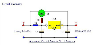
Parts:
R1 = 1R-2W
R2 = 10R-2W
C1 = 35v-470uF
C2 = 35v-470uF
Q1 = TIP2955
IC1 = 78xx Regulator
from http://extremecircuits.blogspot.com
Dual-rail Variable DC Power Supply
Simple add-on for a single-rail supply, ±2.5V to ±15V output
This design was conceived as an add-on for the Variable DC Power Supply, a very successful circuit posted to this website. This simple unit provides a dual-rail variable output ranging from ±2.5V to ±15Vdc with precise tracking of the positive and negative output voltages, still retaining the current limiting and short-proof capabilities of the "master" circuit. As the purpose of such a dual-rail design is to supply experimental or under-repair circuits, the maximum current output delivered was deliberately kept to about 500 - 600mA per rail, thus avoiding the use of expensive power transistors and complex circuitry.

Parts:
R1 = 4.7K-1/2W
R1 = 4.7K-1/2W
C1 = 100nF-63V
C2 = 220µF-25V
C3 = 220µF-25V
C4 = 100nF-63V
C5 = 100nF-63V
Q1 = BD437
Q2 = BD438
IC1 = LM358
Notes:
* The circuit can be placed into the existing Variable DC Power Supply metal cabinet.
* Q1 and Q2 must be mounted on heatsinks. Usually, bolting them to the metal case (through insulating washers etc.) proved effective.
* The full ±15V output can be achieved only if the secondary winding of the supply Transformer used in the Variable DC Power Supply is rated at 48V minimum (center tapped).
* When using this circuit, please set the Current-limit control (P1) of the Variable DC Power Supply to any value comprised in the 50mA - 1A range but not higher.
* The second Op-amp (IC1B) contained in the LM358 chip was not used, but its input pins were tied to the negative supply and the output was left open.
from http://extremecircuits.blogspot.com
Stabilized Regulated Power Supply Circuit
Small and portable circuit, Very useful for Home-Laboratory
This circuit of power supply, is very simple and easy to built, it can be assembled on a general-purpose PCB, finding its materials is very easy and cost-small. The output voltage is stabilized and is regulated in the region from 0V until + 15V dc, with biggest provided current 1 A. The regulation becomes with the P1. The Q1 is classic power transistor and it needs to be placed on a cool rib (Heatsink), when it works continuously in the region of biggest current it gets hot. The type of transformer is standard in the market.

Parts:
P1 = 330R-Potentiometer
R1 = 560R-2W
C1 = 2200uF-35V
C2 = 100uF-35V
C3 = 10uF-25V
C4 = 220uF-25V
C5 = 100nF-63V
D1 = 18V-1.5W Zener
Q1 = 2N3055 NPN Transistor
T1 = 220VAC – 18V@ 1.5A
BR1 = 4x1N4007 Diode Bridge
SW1 = Mains On-Off Switch
from http://extremecircuits.blogspot.com
Variable Dc Power Supply
Voltage Range: 0.7V to 24V, Current Range: 50mA to 2A
A variable dc power supply is one of the most useful tools on the electronics hobbyist's workbench. This circuit is not an absolute novelty, but it is simple, reliable, "rugged" and short-proof, featuring variable voltage up to 24V and variable current limiting up to 2A. You can adapt it to your own requirements as explained in the notes below.
Parts:
P1 = 500R
P2 = 10K
R1 = 2.2K-1/2w
R2 = 2.2K-1/2w
R3 = 330R
R4 = 150R
R5 = 1R-5W
C1 = 35V-3300uF
D1 = 1N5402
D2 = 1N5402
D3 = 5mm Red Led
C2 = 63V-1uF
Q1 = BC182
Q2 = BD139
Q3 = BC212
Q4 = 2N3055
SW1 = SPST Mains Switch
T1 = 36VCT-Transformer
Notes:
* P1 sets the maximum output current you want to be delivered by the power supply at a given output voltage.
* P2 sets the output voltage and must be a logarithmic taper type, in order to obtain a more linear scale voltage indication.
* You can choose the Transformer on the grounds of maximum voltage and current output needed. Best choices are: 36, 40 or 48V center-tapped and 50, 75, 80 or 100VA.
* Capacitor C1 can be 2200 to 6800µF, 35 to 50V.
* Q4 must be mounted on a good heatsink in order to withstand sustained output short-circuit. In some cases the rear panel of the metal box in which you will enclose the circuit can do the job.
* The 2N3055 transistor (Q4) can be replaced with TIP3055 type.
from http://extremecircuits.blogspot.com
A variable dc power supply is one of the most useful tools on the electronics hobbyist's workbench. This circuit is not an absolute novelty, but it is simple, reliable, "rugged" and short-proof, featuring variable voltage up to 24V and variable current limiting up to 2A. You can adapt it to your own requirements as explained in the notes below.

Parts:
P1 = 500R
P2 = 10K
R1 = 2.2K-1/2w
R2 = 2.2K-1/2w
R3 = 330R
R4 = 150R
R5 = 1R-5W
C1 = 35V-3300uF
D1 = 1N5402
D2 = 1N5402
D3 = 5mm Red Led
C2 = 63V-1uF
Q1 = BC182
Q2 = BD139
Q3 = BC212
Q4 = 2N3055
SW1 = SPST Mains Switch
T1 = 36VCT-Transformer
Notes:
* P1 sets the maximum output current you want to be delivered by the power supply at a given output voltage.
* P2 sets the output voltage and must be a logarithmic taper type, in order to obtain a more linear scale voltage indication.
* You can choose the Transformer on the grounds of maximum voltage and current output needed. Best choices are: 36, 40 or 48V center-tapped and 50, 75, 80 or 100VA.
* Capacitor C1 can be 2200 to 6800µF, 35 to 50V.
* Q4 must be mounted on a good heatsink in order to withstand sustained output short-circuit. In some cases the rear panel of the metal box in which you will enclose the circuit can do the job.
* The 2N3055 transistor (Q4) can be replaced with TIP3055 type.
from http://extremecircuits.blogspot.com
1.5 to 35 Volt DC Regulated Power Supply Schematic
Here is the circuit diagram of regulated power supply. It is a small power supply that provides a regulated voltage, adjustable between 1.5 and 35 volts at 1 ampere. The circuit is ready to use, you just need to add a suitable transformer. The circuit is thermal overload protected because the current limiter and thermal overload protection are included in the IC.
The Circuit

circuit diagram

Transformer chart

Parts:
Resistors
R1 = 120R
P1 = 4.7K-Potmeter
Capacitors
C1 = 100nF - 63V
C2 = 1uF - 35V
C3 = 10uF - 35V
C4 = 2200uF - 35V
Semiconductors
IC = LM317
D1 = 1N4007
D2 = 1N4007
D3 = 1N4007
D4 = 1N4007
Features:
* Just add a suitable transformer (see table)
* Great to power your projects and save money on batteries
* Suitable as an adjustable power supply for experiments
* Control DC motors, low voltage light bulbs, …
Specifications :
* Preset any voltage between 1.5 and 35V
* Very low ripple (80dB rejection)
* Short-circuit, thermal and overload protection
* Max input voltage : 28VAC or 40VDC
* Max dissipation : 15W (with heatsink)
* Dimensions : 52x52mm (2.1” x 2.1”)
Note:
* It has not to be cooled if used for small powers. 28 Volt AC max is allowed for the input voltage.
from : http://extremecircuits.blogspot.com
The Circuit

circuit diagram

Transformer chart
Parts:
Resistors
R1 = 120R
P1 = 4.7K-Potmeter
Capacitors
C1 = 100nF - 63V
C2 = 1uF - 35V
C3 = 10uF - 35V
C4 = 2200uF - 35V
Semiconductors
IC = LM317
D1 = 1N4007
D2 = 1N4007
D3 = 1N4007
D4 = 1N4007
Features:
* Just add a suitable transformer (see table)
* Great to power your projects and save money on batteries
* Suitable as an adjustable power supply for experiments
* Control DC motors, low voltage light bulbs, …
Specifications :
* Preset any voltage between 1.5 and 35V
* Very low ripple (80dB rejection)
* Short-circuit, thermal and overload protection
* Max input voltage : 28VAC or 40VDC
* Max dissipation : 15W (with heatsink)
* Dimensions : 52x52mm (2.1” x 2.1”)
Note:
* It has not to be cooled if used for small powers. 28 Volt AC max is allowed for the input voltage.
from : http://extremecircuits.blogspot.com
Super simple inverter
This circuit can be used to power a small strobe or fluorescent lamp. It will generate over 400 VDC from a 12 VDC, 2.5 A power supply or an auto or marine battery. While size, weight, and efficiency are nothing to write home about - in fact, they are quite pitiful - all components are readily available (even from Radio Shack) and construction is very straightforward. No custom coils or transformers are required. If wired correctly, it will work.
Output depends on input voltage. Adjust for your application. With the component values given, it will generate over 400 V from a 12 V supply and charge a 200 uF capacitor to 300 V in under 5 seconds.
For your less intense applications, a fluorescent lamp can be powered directly from the secondary (without any other components). This works reasonably well with a F13-T5 or F15-T12 bulb (but don't expect super brightness). Q1 does get quite hot so use a good heat sink.

Notes on super simple inverter
1. Construction can take any convenient form - perf board, minibox, etc. Make sure the output connections are well insulated.
2. C1 must be nonpolarized type - not an electrolytic.
3. D1 provides a return path for the base drive and prevents significant reverse voltage on the B-E junction. Any 1 A or greater silicon diode should be fine.
4. C2 is shown as typical energy storage capacitor for strobe applications. Remove D2 and C2 for use with a fluorescent lamps.
5. D2 should be a high speed (fast recovery) rectifier. However, for testing, a 1N4007 should work well enough. R2 limits surge current through D2.
6. The polarity of the input with respect to the output leads is important. Select for maximum voltage by interchanging the black output wires.
7. Mount Q1 (2N3055) on a heat sink if continuous operation is desired. I will get warm. Other NPN power transistors with Vceo > 80 V, Ic > 2 A, and Hfe > 15 should work. For a PNP type, reverse the the polarities of the power supply and D1, and interchange one set of leads (where a diode is used for DC output).
8. Some experimentation with component values may improve performance for your application.
9. When testing, use a variable power supply so you get a feel for how much output voltage is produced for each input voltage. Component values are not critical but behavior under varying input/output voltage and load conditions will be affected by R1 and C1 (and the gain of your particular transistor).
10. WARNING: Output is high voltage and dangerous even without large energy storage capacitor. With one, it can be lethal. Take appropriate precautions.
from http://www.repairfaq.org
Adjustable High Voltage Power Supply
This circuit uses a pair of 555 timers to provide variable frequency variable pulse width drive to an inverter using a flyback transformer salvaged from a black and white or color TV or computer monitor.
The input voltage can range from about 5 to 24 V. Using a flyback from a MAC Plus computer which had its bad primary winding excised, an output of more than 20 KV is possible (though risky since the flyback is probably not rated for more than about 12 KV) from a 24 VDC, 2 A power supply. By adjusting the drive
frequency and duty cycle, a wide range of output voltages and currents may be obtained depending on your load.
With the addition of a high voltage filter capacitor (.08 uF, 12 KV), this becomes a nice little helium neon laser power supply which operates on 8 to 15 VDC depending on required tube current and ballast resistor. See the document: "Lasers: Safety, Drive, Info, Parts; Diode, HeNe, Ar/Kr Ion Lasers" for details.
The drive transformer is from a B/W computer monitor (actually a video display terminal) and has a turns ratio of 4:1 wound on a 5/16" square by 3/8" long nylon bobbin on a gapped ferrite double E core. The primary has 80 turns and the secondary has 20 turns, both of #30 wire. Make sure you get the polarity
correct: The base of the switching transistor should be driven when the driver turns on.
Where the flyback includes an internal rectifier and/or you are attempting to obtain the maximum output voltage of a specific polarity, the direction of drive matters as the largest pulse amplitude is generated when the switching transistor turns off. Since flyback transformers are not marked, you will
have to try both possible connections to the drive coil. Use the one that produces the higher output voltage for a given set of input conditions (drive and pulse rate/width).
Many variations on this basic circuit are certainly possible. However, one nice thing about running it at 24 VDC or less is that it is much more difficult to let the smoke out of the circuit! The 5 A power supply I was using shut down on several occasions due to overcurrent but the only time I blew the chopper transistor was by accidentally shorting the base to collector.

from http://www.repairfaq.org
Bug Zapper
You know the type - a purplish light with an occasional (or constant) Zap! Zap! Zap! If you listen real closely, you may be able to hear the screams of the unfortunate insects as well :-).
The high-tech versions consist of a high voltage low current power supply and fluorescent (usually) lamp selected to attract undesirable flying creatures. (Boring low-tech devices may just use a fan to direct the insects to a tray of water from which they are too stupid to be able to excape!)
However, these devices are not selective and will obliterate friendly and useful bugs as well as unwanted pests.
Here is a typical circuit:

This is just a line powered voltage quadrupler. R1 and R2 provide current limiting when the strike occurs (and should someone come in contact with the grid). The lamp, FL1, includes the fluorescent bulb, ballast, and starter (if required). Devices designed for jumbo size bugs (or small rodents) may use
slightly larger capacitors!
from http://www.repairfaq.org
The high-tech versions consist of a high voltage low current power supply and fluorescent (usually) lamp selected to attract undesirable flying creatures. (Boring low-tech devices may just use a fan to direct the insects to a tray of water from which they are too stupid to be able to excape!)
However, these devices are not selective and will obliterate friendly and useful bugs as well as unwanted pests.
Here is a typical circuit:

slightly larger capacitors!
from http://www.repairfaq.org
Electronic Air Cleaner High Voltage ( HV ) Generator
At least I assume this cute little circuit board is for an electronic air cleaner or something similar (dust precipitator, positive/negative ion generator, etc.)! I received the unit (no markings) by mistake in the mail.
However, I did check to make sure it wasn't a bomb before applying power. :-)
This module produces both positive and negative outputs when connected to 115 VAC, 60 Hz line voltage. Each is about 5 KV at up to around 5 uA.

The AC input is rectified by D1 and as it builds up past the threshold of the sidac (D2, 100 V), SCR1 is triggered dumping a small energy storage capacitor (C1) through the primary of the HV transformer, T1. This generates a HV pulse in the secondary. In about .5 ms, the current drops low enough such that the
SCR turns off. As long as the instantaneous input voltage remains above about 100 V, this sequence of events repeats producing a burst of 5 or 6 discharges per cycle of the 60 Hz AC input separated by approximately 13 ms of dead time. The LED (IL1) is a power-on indicator. :-)
The transformer was totally potted so I could not easily determine anything about its construction other than its winding resistances and turns ratio (about 1:100).

The secondary side consists of a voltage tripler for the negative output (HV-) and a simple rectifier for the positive output (HV+). This asymmetry is due to the nature of the unidirectional drive to the transformer primary.
From my measurements, this circuit produces a total of around 10 KV between HV+ and HV-, at up to 5 uA. The output voltages are roughly equal plus and minus when referenced to point B.
I assume the module would also operate on DC (say, 110 to 150 V) with the discharges repeating continuously at about 2 KHz. Output current capability would be about 5 times greater but at the same maximum (no load) voltage. (However, with DC, if the SCR ever got stuck in an 'on' state, it would be
stuck there since there would be no AC zero crossings to force it off. This wouldn't be good!)
The secondary side circuitry can be easily modified or redesigned to provide a single positive or negative output or for higher or lower total voltage. Simply removing R4 will isolate it from the input and earth ground (assuming T1's insulation is adequate).
Where there is no high voltage from such a device, check the following:
* Make sure power is actually getting to the high voltage portion of the unit.
Test the wall socket and/or AC adapter or other power supply for proper
voltage with a multimeter.
* Excessive dirt/dust/muck/moisture or physical damage or a misplaced paper
clip may be shorting it out or resulting in arcing or corona (a strong aroma
of ozone would be an indication of this). With such a small available
current (only uA) it doesn't take much for contamination to be a problem.
Thoroughly clean and dry the unit and check for shorts (with a multimeter
between the HV electrodes and case) and then test it again. Your problems
may be gone!
* If this doesn't help and the unit is not fully potted (in which case,
replacement is the only option), check for shorted or open components,
especially the power semiconductors.
from http://www.repairfaq.org
Auto Air Purifier High Voltage ( HV ) Generator
This thing is about the size of a hot-dog and plugs into the cigarette lighter socket. It produces a bit of ozone and who knows what else. Whether there is any effect on air quality (beneficial or otherwise) or any other effects is questionable but it does contain a nice little high voltage circuit.

T1 is constructed on a 1/4" diameter ferrite core. The D (Drive) and F
(Feedback) windings are wound bifilar style (interleaved) directly on the
core. The O (Output) winding is wound on a nylon sleeve which slips over
the core and is split into 10 sections with an equal number of turns (100
each) with insulation in between them.
DL1 to DL4 look like neon light bulbs with a single electrode. They glow like
neon light bulbs when the circuit is powered and seem to capacitively couple
the HV pulses to the grounded grid in such a way to generate ozone. I don't
know if they are filled with special gas or are just weird neon light bulbs.
from http://www.repairfaq.org
elctronic circuit simulator software
Electronic circuit simulator is computer software that will allow us to design and simulate schematics, electronic projects, circuit designs, and circuit analysis without doing in any actual construction and testing.
Electronic Circuit simulation is very helpful to designers, hobbyists, and students in designing and analyzing the response, behavior and waveforms of circuits without spending money and more time. Since simulation takes place virtually, you can transform your computer into an electronics laboratory where you can design and test circuits.
The compilation of free electronic circuit simulators bellow is useful in designing your electronic projects. Some are totally free to download and free trials.
PSpice Schematics 9.1 a free Student version of electronic circuit simulator PSpice. Very useful in electronic circuit design and analysis but have some limits
LTspice IV a free electronic circuit simulator where you can have schematic capture and waveform viewing. You can also design circuits by simply drag and drop.
Quite Universal Circuit Simulator free circuit simulator software that support all kinds of circuit simulation types, e.g. DC, AC, S-parameter, Transient, Noise and Harmonic Balance analysis. Pure digital simulations are also supported.
TinyCAD is a program for circuit diagrams or schematic drawings. It supports PCB layout programs with several netlist formats and can also produce SPICE simulation netlists.
5Spice provides Spice specific schematic entry, the ability to define and save an unlimited number of analyses and integrated graphing of simulation results. Plus easy inclusion of Spice/PSpice® subcircuits from a user expandable library. The focus is on analog circuit analysis and circuit design at the component level.
NGSPICE project aims to improve the spice3f5 circuit simulator.
LogicCircuit an Educational software for designing and simulating logic circuits, with intuitive GUI, hierarchical circuits and multi bit buses, oscilloscope, and navigate running circuits hierarchy.
ZSPICE is a simple reconfigurable spice simulator. Its device library is created using adms
The free electronic circuit simulators collection above is not owned by the blog author and is subjected by the policy of the rightful owners. Visit the sites of software’s owners for more information
from http://electronician.blogspot.com
Lessons In Electric Circuits.pdf
Great free ebook about electronic circuit provided by Tony R. Kuphaldt, this is a very complete handbook for those who want to learn deeper in electronic/electric circuits. Whether you’re an electrical engineering, mechanical engineering professional, student or college, computer geek or just hobbyist this free ebook is a must download!
Lessons In Electric Circuits covers from basic to advance knowledge in Electrical, including digital circuits and semiconductors, there are many e-books in engineering, but ones that covers electrical engineering in fundamental is limited, this electrical engineering e-book is one of genre said above.
Table of content of the e-book in engineering along with download links:
- Volume I - DC (pdf file, 6 MB)
- Chapter 1: BASIC CONCEPTS OF ELECTRICITY [ contents: Static electricity ~ Conductors, insulators, and electron flow ~ Electric circuits ~ Voltage and current ~ Resistance ~ Voltage and current in a practical circuit ~ Conventional versus electron flow ~ Contributors ]
- Chapter 2: OHM’s LAW [ contents: How voltage, current, and resistance relate ~ An analogy for Ohm's Law ~ Power in electric circuits ~ Calculating electric power ~ Resistors ~ Nonlinear conduction ~ Circuit wiring ~ Polarity of voltage drops ~ Computer simulation of electric circuits ~ Contributors ]
- Chapter 3: ELECTRICAL SAFETY [ contents: The importance of electrical safety ~ Physiological effects of electricity ~ Shock current path ~ Ohm's Law (again!) ~ Safe practices ~ Emergency response ~ Common sources of hazard ~ Safe circuit design ~ Safe meter usage ~ Electric shock data ~ Contributors ]
- Chapter 4: SCIENTIFIC NOTATION AND METRIC PREFIXES [ contents: Scientific notation ~ Arithmetic with scientific notation ~ Metric notation ~ Metric prefix conversions ~ Hand calculator use ~ Scientific notation in SPICE ~ Contributors ]
- Chapter 5: SERIES AND PARALLEL CIRCUITS [ contents: What are "series" and "parallel" circuits? ~ Simple series circuits ~ Simple parallel circuits ~ Conductance ~ Power calculations ~ Correct use of Ohm's Law ~ Component failure analysis ~ Building simple resistor circuits ~ Contributors ]
- Chapter 6: DIVIDER CIRCUITS AND KIRCHHOFF’S LAWS [ contents: Voltage divider circuits ~ Kirchhoff's Voltage Law (KVL) ~ Current divider circuits ~ Kirchhoff's Current Law (KCL) ~ Contributors ]
- Chapter 7: SERIES-PARALLEL COMBINATION CIRCUITS [ contents: What is a series-parallel circuit? ~ Analysis technique ~ Re-drawing complex schematics ~ Component failure analysis ~ Building series-parallel resistor circuits ~ Contributors ]
- Chapter 8: DC METERING CIRCUITS [ contents: What is a meter? ~ Voltmeter design ~ Voltmeter impact on measured circuit ~ Ammeter design ~ Ammeter impact on measured circuit ~ Ohmmeter design ~ High voltage ohmmeters ~ Multimeters ~ Kelvin (4-wire) resistance measurement ~ Bridge circuits ~ Wattmeter design ~ Creating custom calibration resistances ~ Contributors ]
- Chapter 9: ELECTRICAL INSTRUMENTATION SIGNALS [ contents: Analog and digital signals ~ Voltage signal systems ~ Current signal systems ~ Tachogenerators ~ Thermocouples ~ pH measurement ~ Strain gauges ~ Contributors ]
- Chapter 10: DC NETWORK ANALYSIS [ contents: What is network analysis? ~ Branch current method ~ Mesh current method ~ Node voltage method ~ Introduction to network theorems ~ Millman's Theorem ~ Superposition Theorem ~ Thevenin's Theorem ~ Norton's Theorem ~ Thevenin-Norton equivalencies ~ Millman's Theorem revisited ~ Maximum Power Transfer Theorem ~ -Y and Y- conversions ~ Contributors ]
- Chapter 11: BATTERIES AND POWER SYSTEMS [ contents: Electron activity in chemical reactions ~ Battery construction ~ Battery ratings ~ Special-purpose batteries ~ Practical considerations ~ Contributors ]
- Chapter 12: PHYSICS OF CONDUCTORS AND INSULATORS [ contents: Introduction ~ Conductor size ~ Conductor ampacity ~ Fuses ~ Specific resistance ~ Temperature coefficient of resistance ~ Superconductivity ~ Insulator breakdown voltage ~ Data ~ Contributors ]
- Chapter 13: CAPACITORS [ contents: Electric fields and capacitance ~ Capacitors and calculus ~ Factors affecting capacitance ~ Series and parallel capacitors ~ Practical considerations ~ Contributors ]
- Chapter 14: MAGNETISM AND ELECTROMAGNETISM [ contents: Permanent magnets ~ Electromagnetism ~ Magnetic units of measurement ~ Permeability and saturation ~ Electromagnetic induction ~ Mutual inductance ~ Contributors ]
- Chapter 15: INDUCTORS [ contents: Magnetic fields and inductance ~ Inductors and calculus ~ Factors affecting inductance ~ Series and parallel inductors ~ Practical considerations ~ Contributors ]
- Chapter 16: RC AND L/R TIME CONSTANTS [ contents: Electrical transients ~ Capacitor transient response ~ Inductor transient response ~ Voltage and current calculations ~ Why L/R and not LR? ~ Complex voltage and current calculations ~ Complex circuits ~ Solving for unknown time ~ Contributors ]
- Chapter 17: CONTRIBUTOR LIST [ contents: How to contribute to this book ~ Credits ]
- Volume II - AC (pdf file, 3 MB)
- Chapter 1: BASIC AC THEORY [ contents: What is alternating current (AC)? ~ AC waveforms ~ Measurements of AC magnitude ~ Simple AC circuit calculations ~ AC phase ~ Principles of radio ~ Contributors ]
- Chapter 2: COMPLEX NUMBERS [ contents: Introduction ~ Vectors and AC waveforms ~ Simple vector addition ~ Complex vector addition ~ Polar and rectangular notation ~ Complex number arithmetic ~ More on AC "polarity" ~ Some examples with AC circuits ~ Contributors ]
- Chapter 3: REACTANCE AND IMPEDANCE — INDUCTIVE [ contents: AC resistor circuits ~ AC inductor circuits ~ Series resistor-inductor circuits ~ Parallel resistor-inductor circuits ~ Inductor quirks ~ More on the ``skin effect'' ~ Contributors ]
- Chapter 4: REACTANCE AND IMPEDANCE — CAPACITIVE [ contents: AC resistor circuits ~ AC capacitor circuits ~ Series resistor-capacitor circuits ~ Parallel resistor-capacitor circuits ~ Capacitor quirks ~ Contributors ]
- Chapter 5: REACTANCE AND IMPEDANCE — R, L, AND C [ contents: Review of R, X, and Z ~ Series R, L, and C ~ Parallel R, L, and C ~ Series-parallel R, L, and C ~ Susceptance and Admittance ~ Summary ~ Contributors ]
- Chapter 6: RESONANCE [ contents: An electric pendulum ~ Simple parallel (tank circuit) resonance ~ Simple series resonance ~ Applications of resonance ~ Resonance in series-parallel circuits ~ Q and bandwidth of a resonant circuit ~ Contributors ]
- Chapter 7: MIXED-FREQUENCY AC SIGNALS [ contents: Introduction ~ Square wave signals ~ Other waveshapes ~ More on spectrum analysis ~ Circuit effects ~ Contributors ]
- Chapter 8: FILTERS [ contents: What is a filter? ~ Low-pass filters ~ High-pass filters ~ Band-pass filters ~ Band-stop filters ~ Resonant filters ~ Summary ~ Contributors ]
- Chapter 9: TRANSFORMERS [ contents: Mutual inductance and basic operation ~ Step-up and step-down transformers ~ Electrical isolation ~ Phasing ~ Winding configurations ~ Voltage regulation ~ Special transformers and applications ~ Practical considerations ~ Contributors ]
- Chapter 10: POLYPHASE AC CIRCUITS [ contents: Single-phase power systems ~ Three-phase power systems ~ Phase rotation ~ Polyphase motor design ~ Three-phase Y and configurations ~ Three-phase transformer circuits ~ Harmonics in polyphase power systems ~ Harmonic phase sequences ~ Contributors ]
- Chapter 11: POWER FACTOR [ contents: Power in resistive and reactive AC circuits ~ True, Reactive, and Apparent power ~ Calculating power factor ~ Practical power factor correction ~ Contributors ]
- Chapter 12: AC METERING CIRCUITS [ contents: AC voltmeters and ammeters ~ Frequency and phase measurement ~ Power measurement ~ Power quality measurement ~ AC bridge circuits ~ AC instrumentation transducers ~ Contributors ]
- Chapter 13: AC MOTORS [ contents: Introduction ~ Synchronous Motors ~ Synchronous condenser ~ Reluctance motor ~ Stepper motors ~ Brushless DC motor ~ Tesla polyphase induction motors ~ Wound rotor induction motors ~ Single-phase induction motors ~ Other specialized motors ~ Selsyn (synchro) motors ~ AC commutator motors ]
- Chapter 14: TRANSMISSION LINES [ contents: A 50-ohm cable? ~ Circuits and the speed of light ~ Characteristic impedance ~ Finite-length transmission lines ~ ``Long'' and ``short'' transmission lines ~ Standing waves and resonance ~ Impedance transformation ~ Waveguides ]
- Chapter 15: CONTRIBUTOR LIST [ contents: How to contribute to this book ~ Credits ]
- Volume III - Semiconductors (pdf file, 3.8 MB)
- Chapter 1: AMPLIFIERS AND ACTIVE DEVICES [ contents: From electric to electronic ~ Active versus passive devices ~ Amplifiers ~ Amplifier gain ~ Decibels ~ Absolute dB scales ~ Attenuators ]
- Chapter 2: SOLID-STATE DEVICE THEORY [ contents: Introduction ~ Quantum physics ~ Valence and Crystal structure ~ Band theory of solids ~ Electrons and ``holes'' ~ The P-N junction ~ Junction diodes ~ Bipolar junction transistors ~ Junction field-effect transistors ~ Insulated-gate field-effect transistors (MOSFET) ~ Thyristors ~ Semiconductor manufacturing techniques ~ Superconducting devices ~ Quantum devices ~ Semiconductor devices in SPICE ]
- Chapter 3: DIODES AND RECTIFIERS [ contents: Introduction ~ Meter check of a diode ~ Diode ratings ~ Rectifier circuits ~ Peak detector ~ Clipper circuits ~ Clamper circuits ~ Voltage multipliers ~ Inductor commutating circuits ~ Diode switching circuits ~ Zener diodes ~ Special-purpose diodes ~ Other diode technologies ~ SPICE models ]
- Chapter 4: BIPOLAR JUNCTION TRANSISTORS [ contents: Introduction ~ The transistor as a switch ~ Meter check of a transistor ~ Active mode operation ~ The common-emitter amplifier ~ The common-collector amplifier ~ The common-base amplifier ~ Biasing techniques ~ Input and output coupling ~ Feedback ~ Amplifier impedances ~ Current mirrors ~ Transistor ratings and packages ~ BJT quirks ]
- Chapter 5: JUNCTION FIELD-EFFECT TRANSISTORS [ contents: Introduction ~ The transistor as a switch ~ Meter check of a transistor ~ Active-mode operation ~ The common-source amplifier -- PENDING ~ The common-drain amplifier -- PENDING ~ The common-gate amplifier -- PENDING ~ Biasing techniques -- PENDING ~ Transistor ratings and packages -- PENDING ~ JFET quirks -- PENDING ]
- Chapter 6: INSULATED-GATE FIELD-EFFECT TRANSISTORS [ contents: Introduction ~ Depletion-type IGFETs ~ Enhancement-type IGFETs -- PENDING ~ Active-mode operation -- PENDING ~ The common-source amplifier -- PENDING ~ The common-drain amplifier -- PENDING ~ The common-gate amplifier -- PENDING ~ Biasing techniques -- PENDING ~ Transistor ratings and packages -- PENDING ~ IGFET quirks -- PENDING ~ MESFETs -- PENDING ~ IGBTs ]
- Chapter 7: THYRISTORS [ contents: Hysteresis ~ Gas discharge tubes ~ The Shockley Diode ~ The DIAC ~ The Silicon-Controlled Rectifier (SCR) ~ The TRIAC ~ Optothyristors ~ The Unijunction Transistor (UJT) -- PENDING ~ The Silicon-Controlled Switch (SCS) ~ Field-effect-controlled thyristors ]
- Chapter 8: OPERATIONAL AMPLIFIERS [ contents: Introduction ~ Single-ended and differential amplifiers ~ The "operational" amplifier ~ Negative feedback ~ Divided feedback ~ An analogy for divided feedback ~ Voltage-to-current signal conversion ~ Averager and summer circuits ~ Building a differential amplifier ~ The instrumentation amplifier ~ Differentiator and integrator circuits ~ Positive feedback ~ Practical considerations ~ Operational amplifier models ~ Data ]
- Chapter 9: PRACTICAL ANALOG SEMICONDUCTOR CIRCUITS [ contents: ElectroStatic Discharge ~ Power supply circuits -- INCOMPLETE ~ Amplifier circuits -- PENDING ~ Oscillator circuits -- INCOMPLETE ~ Phase-locked loops -- PENDING ~ Radio circuits -- INCOMPLETE ~ Computational circuits ~ Measurement circuits -- INCOMPLETE ~ Control circuits -- PENDING ]
- Chapter 10: ACTIVE FILTERS
- Chapter 11: DC MOTOR DRIVES
- Chapter 12: INVERTERS AND AC MOTOR DRIVES
- Chapter 13: ELECTRON TUBES [ contents: Introduction ~ Early tube history ~ The triode ~ The tetrode ~ Beam power tubes ~ The pentode ~ Combination tubes ~ Tube parameters ~ Ionization (gas-filled) tubes ~ Display tubes ~ Microwave tubes ~ Tubes versus Semiconductors ]
- Chapter 14: CONTRIBUTOR LIST [ contents: How to contribute to this book ~ Credits ]
- Volume IV - Digital (pdf file, 2.75 MB)
- Chapter 1: NUMERATION SYSTEMS [ contents: Numbers and symbols ~ Systems of numeration ~ Decimal versus binary numeration ~ Octal and hexadecimal numeration ~ Octal and hexadecimal to decimal conversion ~ Conversion from decimal numeration ]
- Chapter 2: BINARY ARITHMETIC [ contents: Numbers versus numeration ~ Binary addition ~ Negative binary numbers ~ Subtraction ~ Overflow ~ Bit groupings ]
- Chapter 3: LOGIC GATES [ contents: Digital signals and gates ~ The NOT gate ~ The "buffer" gate ~ Multiple-input gates ~ TTL NAND and AND gates ~ TTL NOR and OR gates ~ CMOS gate circuitry ~ Special-output gates ~ Gate universality ~ Logic signal voltage levels ~ DIP gate packaging ~ Contributors ]
- Chapter 4: SWITCHES [ contents: Switch types ~ Switch contact design ~ Contact "normal" state and make/break sequence ~ Contact "bounce" ]
- Chapter 5: ELECTROMECHANICAL RELAYS [ contents: Relay construction ~ Contactors ~ Time-delay relays ~ Protective relays ~ Solid-state relays ]
- Chapter 6: LADDER LOGIC [ contents: "Ladder" diagrams ~ Digital logic functions ~ Permissive and interlock circuits ~ Motor control circuits ~ Fail-safe design ~ Programmable logic controllers ~ Contributors ]
- Chapter 7: BOOLEAN ALGEBRA [ contents: Introduction ~ Boolean arithmetic ~ Boolean algebraic identities ~ Boolean algebraic properties ~ Boolean rules for simplification ~ Circuit simplification examples ~ The Exclusive-OR function ~ DeMorgan's Theorems ~ Converting truth tables into Boolean expressions ]
- Chapter 8: KARNAUGH MAPPING [ contents: Introduction ~ Venn diagrams and sets ~ Boolean Relationships on Venn Diagrams ~ Making a Venn diagram look like a Karnaugh map ~ Karnaugh maps, truth tables, and Boolean expressions ~ Logic simplification with Karnaugh maps ~ Larger 4-variable Karnaugh maps ~ Minterm vs maxterm solution ~ (sum) and (product) notation ~ Don't care cells in the Karnaugh map ~ Larger 5 & 6-variable Karnaugh maps ]
- Chapter 9: COMBINATIONAL LOGIC FUNCTIONS [ contents: Introduction ~ A Half-Adder ~ A Full-Adder ~ Decoder ~ Encoder ~ Demultiplexers ~ Multiplexers ~ Using multiple combinational circuits ]
- Chapter 10: MULTIVIBRATORS [ contents: Digital logic with feedback ~ The S-R latch ~ The gated S-R latch ~ The D latch ~ Edge-triggered latches: Flip-Flops ~ The J-K flip-flop ~ Asynchronous flip-flop inputs ~ Monostable multivibrators ]
- Chapter 11: COUNTERS [ contents: Binary count sequence ~ Asynchronous counters ~ Synchronous counters ~ Counter modulus ]
- Chapter 12: SHIFT REGISTERS [ contents: Introduction ~ Serial-in/serial-out shift register ~ Parallel-in, serial-out shift register ~ Serial-in, parallel-out shift register ~ Parallel-in, parallel-out, universal shift register ~ Ring counters ~ references ]
- Chapter 13: DIGITAL-ANALOG CONVERSION [ contents: Introduction ~ The R/2nR DAC ~ The R/2R DAC ~ Flash ADC ~ Digital ramp ADC ~ Successive approximation ADC ~ Tracking ADC ~ Slope (integrating) ADC ~ Delta-Sigma () ADC ~ Practical considerations of ADC circuits ]
- Chapter 14: DIGITAL COMMUNICATION [ contents: Introduction ~ Networks and busses ~ Data flow ~ Electrical signal types ~ Optical data communication ~ Network topology ~ Network protocols ~ Practical considerations ]
- Chapter 15: DIGITAL STORAGE (MEMORY) [ contents: Why digital? ~ Digital memory terms and concepts ~ Modern nonmechanical memory ~ Historical, nonmechanical memory technologies ~ Read-only memory ~ Memory with moving parts: "Drives" ]
- Chapter 16: PRINCIPLES OF DIGITAL COMPUTING [ contents: A binary adder ~ Look-up tables ~ Finite-state machines ~ Microprocessors ~ Microprocessor programming ]
- Chapter 17: CONTRIBUTOR LIST [ contents: How to contribute to this book ~ Credits ]
- Volume V - Reference (pdf file, 0.7 MB)
- Chapter 1: USEFUL EQUATIONS AND CONVERSION FACTORS [ contents: DC circuit equations and laws ~ Series circuit rules ~ Parallel circuit rules ~ Series and parallel component equivalent values ~ Capacitor sizing equation ~ Inductor sizing equation ~ Time constant equations ~ AC circuit equations ~ Decibels ~ Metric prefixes and unit conversions ~ Data ~ Contributors ]
- Chapter 2: COLOR CODES [ contents: Resistor Color Codes ~ Wiring Color Codes ]
- Chapter 3: CONDUCTOR AND INSULATOR TABLES [ contents: Copper wire gage table ~ Copper wire ampacity table ~ Coefficients of specific resistance ~ Temperature coefficients of resistance ~ Critical temperatures for superconductors ~ Dielectric strengths for insulators ~ Data ]
- Chapter 4: ALGEBRA REFERENCE [ contents: Basic identities ~ Arithmetic properties ~ Properties of exponents ~ Radicals ~ Important constants ~ Logarithms ~ Factoring equivalencies ~ The quadratic formula ~ Sequences ~ Factorials ~ Solving simultaneous equations ~ Contributors ]
- Chapter 5: TRIGONOMETRY REFERENCE [ contents: Right triangle trigonometry ~ Non-right triangle trigonometry ~ Trigonometric equivalencies ~ Hyperbolic functions ~ Contributors ]
- Chapter 6: CALCULUS REFERENCE [ contents: Rules for limits ~ Derivative of a constant ~ Common derivatives ~ Derivatives of power functions of e ~ Trigonometric derivatives ~ Rules for derivatives ~ The antiderivative (Indefinite integral) ~ Common antiderivatives ~ Antiderivatives of power functions of e ~ Rules for antiderivatives ~ Definite integrals and the fundamental theorem of calculus ~ Differential equations ]
- Chapter 7: USING THE SPICE CIRCUIT SIMULATION PROGRAM [ contents: Introduction ~ History of SPICE ~ Fundamentals of SPICE programming ~ The command-line interface ~ Circuit components ~ Analysis options ~ Quirks ~ Example circuits and netlists ]
- Chapter 8: TROUBLESHOOTING — THEORY AND PRACTICE [ contents: Questions to ask before proceeding ~ General troubleshooting tips ~ Specific troubleshooting techniques ~ Likely failures in proven systems ~ Likely failures in unproven systems ~ Potential pitfalls ~ Contributors ]
- Chapter 9: CIRCUIT SCHEMATIC SYMBOLS [ contents: Wires and connections ~ Power sources ~ Resistors ~ Capacitors ~ Inductors ~ Mutual inductors ~ Switches, hand actuated ~ Switches, process actuated ~ Switches, electrically actuated (relays) ~ Connectors ~ Diodes ~ Transistors, bipolar ~ Transistors, junction field-effect (JFET) ~ Transistors, insulated-gate field-effect (IGFET or MOSFET) ~ Transistors, hybrid ~ Thyristors ~ Integrated circuits ~ Electron tubes ]
- Chapter 10: PERIODIC TABLE OF THE ELEMENTS [ contents: Table (landscape view) ~ Table (portrait view) ~ Data ]
- Chapter 11: CONTRIBUTOR LIST [ contents: How to contribute to this book ~ Credits ]
- Volume VI - Experiments (pdf file, 3.7 MB)
- Chapter 1: INTRODUCTION [ contents: Electronics as science ~ Setting up a home lab ~ Contributors ]
- Chapter 2: BASIC CONCEPTS AND TEST EQUIPMENT [ contents: Voltmeter usage ~ Ohmmeter usage ~ A very simple circuit ~ Ammeter usage ~ Ohm's Law ~ Nonlinear resistance ~ Power dissipation ~ Circuit with a switch ~ Electromagnetism ~ Electromagnetic induction ]
- Chapter 3: DC CIRCUITS [ contents: Introduction ~ Series batteries ~ Parallel batteries ~ Voltage divider ~ Current divider ~ Potentiometer as a voltage divider ~ Potentiometer as a rheostat ~ Precision potentiometer ~ Rheostat range limiting ~ Thermoelectricity ~ Make your own multimeter ~ Sensitive voltage detector ~ Potentiometric voltmeter ~ 4-wire resistance measurement ~ A very simple computer ~ Potato battery ~ Capacitor charging and discharging ~ Rate-of-change indicator ]
- Chapter 4: AC CIRCUITS [ contents: Introduction ~ Transformer -- power supply ~ Build a transformer ~ Variable inductor ~ Sensitive audio detector ~ Sensing AC magnetic fields ~ Sensing AC electric fields ~ Automotive alternator ~ Induction motor ~ Phase shift ~ Sound cancellation ~ Musical keyboard as a signal generator ~ PC Oscilloscope ~ Waveform analysis ~ Inductor-capacitor "tank" circuit ~ Signal coupling ]
- Chapter 5: DISCRETE SEMICONDUCTOR CIRCUITS [ contents: Introduction ~ Commutating diode ~ Half-wave rectifier ~ Full-wave center-tap rectifier ~ Full-wave bridge rectifier ~ Rectifier/filter circuit ~ Voltage regulator ~ Transistor as a switch ~ Static electricity sensor ~ Pulsed-light sensor ~ Voltage follower ~ Common-emitter amplifier ~ Multi-stage amplifier ~ Current mirror ~ JFET current regulator ~ Differential amplifier ~ Simple op-amp ~ Audio oscillator ~ Vacuum tube audio amplifier ]
- Chapter 6: ANALOG INTEGRATED CIRCUITS [ contents: Introduction ~ Voltage comparator ~ Precision voltage follower ~ Noninverting amplifier ~ High-impedance voltmeter ~ Integrator ~ 555 audio oscillator ~ 555 ramp generator ~ PWM power controller ~ Class B audio amplifier ]
- Chapter 7: DIGITAL INTEGRATED CIRCUITS [ contents: Introduction ~ Basic gate function ~ NOR gate S-R latch ~ NAND gate S-R enabled latch ~ NAND gate S-R flip-flop ~ LED sequencer ~ Simple combination lock ~ 3-bit binary counter ~ 7-segment display ]
- Chapter 8: CONTRIBUTOR LIST [ contents: How to contribute to this book ~ Credits ]
Copyright (C) 2000-2007, Tony R. Kuphaldt.
from http://www.onlinefreeebooks.net
Basic Electrical Technology ( Three phase induction motor, D.C Machines , Measuring instruments ) module 8 , 9 and 10
- Module-8 Three phase induction motor
- Lesson 29 Rotating Magnetic Field in Three-phase Induction Motor [ Three-phase Induction Motor ~ Rotating Magnetic Field ~ Four-Pole Stator ~ The Reversal of Direction of Rotating Magnetic Field ]
- Lesson 30 Construction and Principle of Operation of IM [ Construction of Three-phase Induction Motor ~ Principle of Operation ~ The frequency of the induced emf and current in the rotor ]
- Lesson 31 Equivalent Circuit and Power Flow Diagram of IM [ The induced emf per phase, in the motor windings ~ The equivalent circuit per phase, of the rotor ~ The relation between rotor input, rotor copper loss and rotor output ~ Power flow diagram ]
- Lesson 32 Torque-Slip (speed) Characteristics of Induction Motor (IM) [ Gross Torque Developed ~ Torque-slip (speed) Characteristics ~ Starting Current and Torque ]
- Lesson 33 Different Types of Starters for Induction Motor (IM) [ Direct-on-Line (DOL) Starters ~ Need for Starters in IM ~ Starters for Cage IM ~ Rotor Resistance Starters for Slip-ring (wound rotor) IM ]
- Lesson 34 Starting Methods for Single-phase Induction Motor [ Single-phase Induction Motor ~ Double field revolving theory ~ Starting Methods ~ Resistance Split-phase Motor ~ Capacitor Split-phase Motor ~ Capacitor-start Motor ~ Capacitor-start and Capacitor-run Motor ~ Shaded-pole Motor ]
- Module-9 D.C Machines
- Lesson 35 Constructional Features of D.C Machines [ Constructional Features ~ D.C machine Armature Winding ~ Armature winding: General procedure ~ Developed diagram ~ Lap winding ~ Another example of Lap winding ~ Wave winding ]
- Lesson 36 Principle of Operation of D.C Machines [ Example of Single conductor Generator & Motor ~ Rotating Machines ~ Driving & Opposing torques ~ Generator mode ~ Motor mode ~ Condition for steady production of torque ~ D.C generator: Basic principle of operation ~ D.C motor: Basic principle of operation ]
- Lesson 37 EMF & Torque Equation [ EMF & Torque Equations ~ EMF Equation ~ Torque Equation ~ GNP and MNP ~ Armature reaction ~ No Load operation ~ Loaded operation ~ Cross magnetizing & Demagnetizing AT ~ Commutation & Armature reaction ]
- Lesson 38 D.C Generators [ Generator types & characteristics ~ Characteristics of a separately excited generator ~ Characteristics of a shunt generator ~ Load characteristic of shunt generator ~ Prediction of approximate load characteristic from OCC & Rf line ~ Compound generator ]
- Lesson 39 D.C Motors [ Starting of D.C shunt motor ~ Problems of starting with full voltage ~ A simple starter ~ 3-point starter ~ Speed control of shunt motor ~ Speed control by varying armature resistance ~ Speed control by varying field current ~ Speed control by armature voltage variation ~ Ward Leonard method: combination of Va and If control ~ Series motor ~ Characteristics of series motor ~ Speed control of series motor ~ Speed control below base speed ~ Speed control above base speed ~ Braking of d.c shunt motor: basic idea ~ Rheostatic braking ~ Plugging or dynamic braking ~ Regenerative braking ]
- Lesson 40 Losses, Efficiency and Testing of D.C. Machines [ Major losses ~ Swinburne's Test ~ Hopkinson's test ~ Procedure ~ Loading the machines ~ Calculation of efficiency ~ Condition for maximum efficiency ~ Maximum efficiency for motor mode ~ Maximum efficiency for General mode ]
- Lesson 41 Problem Solving on D.C Machines [ Shunt motor problems ~ Problems on Series Motor ~ D.C generator problems ~ Operation of d.c machine connected to d.c bus (fixed d.c voltage) ]
- Module-10 Measuring instruments
- Lesson 42 Study of DC-AC Measuring Instruments [ Various forces/torques required in measuring instruments ~ General Theory Permanent Magnet Moving Coil (PMMC) Instruments ~ A multi-range ammeters and voltmeters ~ Advantages, Limitations and sources of errors ~ Construction and Basic principle operation of Moving-iron Instruments ~ Construction of Moving-iron Instruments ~ Ranges of Ammeters and Voltmeters ]
- Lesson 43 Study of Electro-Dynamic Type Instruments [ Operating Principle ~ More about ammeters ~ Ranges of Ammeters and Voltmeters ~ Connections for ammeter, voltmeter and wattmeter ~ Inductance of Voltage-Coil Introduces an Error in Wattmeter ~ Advantages and disadvantages of electro-dynamic instruments ]
- Lesson 44 Study of Single Phase Induction Type Energy Meter or Watt-hour Meter [ Construction of induction type energy meter ~ Errors in the energy meter ~ Extension of Instrument Range ]
from http://www.onlinefreeebooks.net
Basic Electrical Technology ( Three phase AC ,Magnetic circuits & Core losses, Transformer ) module 5,8and 7
- Module-5 Three phase AC circuits
- Lesson 18 Three-phase Balanced Supply [ Generation of Three-phase Balanced Voltages ~ Three-phase Voltages for Star Connection ~ Reversal of phase sequence from R-Y-B to R-B-Y ~ Relation between the Phase and Line Voltages for Star Connection ~ Relation between the Phase and Line Voltages for Delta Connection ~ Currents for Circuit with Balanced Load (Star-connected) ~ Total Power Consumed in the Circuit (Star-connected) ~ Delta(ÃŽ")-Star(Y) conversion and Star-Delta conversion ]
- Lesson 19 Three-phase Delta-Connected Balanced Load [ Currents for Circuits with Balanced Load (Delta-connected) ~ Total Power Consumed in the Circuit (Delta-connected) ]
- Lesson 20 Measurement of Power in a Three-phase Circuit [ Two-wattmeter Method of Power Measurement in a Three-phase Circuit ~ Phasor diagram for a three-phase balanced star-connected circuit ]
- Module-6 Magnetic circuits & Core losses
- Lesson 21 Magnetic Circuits [ Different laws for calculating magnetic field ~ Biot-Savart law ~ Ampere's circuital law ~ Application of Ampere's circuital law in magnetic circuit ~ Reluctance & permeance ~ B-H Characteristics ~ Different zones of B-H characteristic ~ Analysis of Series magnetic circuit ~ Analysis of Series-parallel magnetic circuit ~ Important equations ~ General discussion on solving problems ~ Worked out example ]
- Lesson 22 Eddy Current & Hysteresis Loss [ Voltage induced in a stationary coil placed in a time varying field ~ Eddy current ~ Use of thin plates or laminations for core ~ Derivation of an expression for eddy current loss in a thin plate ~ Hysteresis Loss ~ Undirectional time varying exciting current ~ Energy stored, energy returned & energy density ~ Hysteresis loop with alternating exciting current ~ Hysteresis loss & loop area ~ Seperation of core loss ~ Inductor ~ Force between two opposite faces of the core across an air gap ]
- Module-7 Transformer
- Lesson 23 Ideal Transformer [ Ideal Transformer ~ Core flux gets fixed by voltage and frequency ~ Analysis of ideal transformer ~ No load phasor diagram ~ Transformer under loaded condition ~ Dot convention ~ Equivalent circuit of an ideal transformer ]
- Lesson 24 Practical Transformer [ Practical transformer ~ Core loss ~ Taking core loss into account ~ Taking winding resistances and leakage flux into account ~ A few words about equivalent circuit ]
- Lesson 25 Testing, Efficiency & Regulation [ Determination of equivalent circuit parameters ~ Qualifying parameters with suffixes LV & HV ~ Open Circuit Test ~ Short circuit test ~ Efficiency of transformer ~ All day efficiency ~ Regulation ]
- Lesson 26 Three Phase Transformer [ Three phase transformer ~ Introducing basic ideas ~ A wrong star-star connection ~ Bank of three phase transformer ~ 3-phase transformer - a single unit ~ Vector Group of 3-phase transformer ]
- Lesson 27 Auto-Transformer [ 2-winding transformer as Autotransformer ~ Autotransformer as a single unit ]
- Lesson 28 Problem solving on Transformers [ Problems on 2 winding single phase transformers ~ Problems on 3-phase ideal transformer ~ Problems on ideal auto transformers ]
from http://www.onlinefreeebooks.net
Basic Electrical Technology ( R-L & R-C Transients and Single phase A.C) module 3 and 4
- Module-3 R-L & R-C Transients
- Lesson 10 Study of DC transients in R-L and R-C circuits [ Significance of Inductance of a coil and dc transients in a simple R-L circuit ~ Inductance calculation from physical dimension of coil ~ Continuity condition of Inductors ~ Study of dc transients and steady state response of a series R-L circuit. ~ Growth or Rise of current in R-L circuit ~ Fall or Decay of current in a R-L circuit ~ Energy stored in an inductor ~ Capacitor and its behavior ~ Continuity condition of capacitors ~ Study of dc transients and steady state response of a series R-C circuit. ~ Charging of a capacitor or Growth of a capacitor voltage in dc circuits ~ Discharging of a capacitor or Fall of a capacitor voltage in dc circuits ~ Energy stored in a capacitor ]
- Lesson 11 Study of DC transients in R-L-C Circuits [ Response of a series R-L-C circuit due to a dc voltage source ~ Average and RMS Values of Sinusoidal Voltage Waveform ]
- Module-4 Single phase A.C circuits
- Lesson 12 Generation of Sinusoidal Voltage Waveform (AC) and Some Fundamental Concepts [ Generation of Sinusoidal (AC) Voltage Waveform ~ Periodic Voltage or Current Waveform ]
- Lesson 13 Representation of Sinusoidal Signal by a Phasor and Solution of Current in R-L-C Series Circuits [ Representation of Sinusoidal Signal by a Phasor ~ Generalized case ~ Phasor representation of Voltage and Current ~ Phasor Algebra ~ Representation of a phasor and Transformation ~ Addition/Subtraction of Phasors ~ Multiplication/Division of Phasors ]
- Lesson 14 Solution of Current in R-L-C Series Circuits [ Solution of Steady State Current in Circuits Fed from Single-phase AC Supply ~ Elementary Circuits ~ Series Circuits ~ Power consumed and Power factor ~ Complex Power, Volt-Amperes (VA) and Reactive Power ]
- Lesson 15 Solution of Current in AC Series and Parallel Circuits [ Solution of Current in R-L-C Series Circuit ~ Solution of Current in Parallel Circuit ]
- Lesson 16 Solution of Current in AC Parallel and Series-parallel Circuits [ Solution of Current in Series-parallel Circuit ]
- Lesson 17 Resonance in Series and Parallel Circuits [ Resonance in Series and Parallel Circuits ]
from http://www.onlinefreeebooks.net
Basic Electrical Technology (DC circuits) module 1 and 2
Other course material in pdf file from EE IIT Kharagpur, about Basic Electrical Technology. Consist of 44 Lessons, in 44 pdf files. It’s a good kickstart for one who want to know deeper about electric circuit, transformer, motors, three phase electricity etc.
Welcome to this course on Basic Electrical Technology. Engineering students of almost all disciplines has to undergo this course (name may be slightly different in different course curriculum) as a core subject in the first semester. It is needless to mention that how much we are dependent on electricity in our day to day life. A reasonable understanding on the basics of applied electricity is therefore important for every engineer.
Apart from learning d.c and a.c circuit analysis both under steady state and transient conditions, you will learn basic working principles and analysis of transformer, d.c motors and induction motor. Finally working principles of some popular and useful indicating measuring instruments are presented.
The course can be broadly divided into 3 major parts, namely: Electrical circuits, Electrical Machines and Measuring instruments. The course is spread over 10 modules covering these 3-parts, each module having two or more lessons under it as detailed below.
- Module 1 Introduction
- Lesson 1 Introducing the Course on Basic Electrical
- Lesson 2 Generation, Transmission and Distribution of Electric Power an Overview [ Basic idea of generation ~ Changeover from D.C to A.C ~ A.C generator ~ Thermal, hyddel & nuclear power stations ~ Thermal plant ~ Hydel plants ~ Nuclear plants ~ Transmission of power ~ Single line representation of power system ~ Distribution system ]
- Module-2 D.C. circuits
- Lesson 3 Introduction of Electric Circuit [ Basic Elements & Introductory Concepts ~ Linear and Nonlinear Circuits ~ Kirchhoff's Laws ~ Meaning of Circuit Ground and the Voltages referenced to Ground ~ Understanding the Basic Principles of Voltage Dividers ~ Potentiometer and its function ~ Practical Voltage and Current Sources ~ Independent and Dependent Sources that encountered in electric circuits ~ Understanding Delivering and Absorbing Power by the Source.]
- Lesson 4 Loop Analysis of resistive circuit in the context of dc voltages and currents [ Solution of Electric Circuit Based on Mesh (Loop) Current Method ]
- Lesson 5 Node-voltage analysis of resistive circuit in the context of dc voltages and currents [ Node voltage analysis ~ Solution of Electric Circuit Based on Node Voltage Method ]
- Lesson 6 Wye (Y) - Delta (ÃŽ”) OR Delta (ÃŽ”)-Wye (Y) Transformations [ Delta (ÃŽ") - Wye (Y) conversion ~ Conversion from Delta (ÃŽ") to Star or Wye (Y) ~ Conversion from Star or Wye (Y) to Delta (ÃŽ") ~ Application of Star ()Y to Delta ÃŽ"() or Delta ÃŽ"() to Star ()Y Transformation ]
- Lesson 7 Superposition Theorem in the context of dc voltage and current sources acting in a resistive network [ Statement of superposition theorem ~ Procedure for using the superposition theorem ~ Application of superposition theorem ~ Limitations of superposition Theorem ]
- Lesson 8 Thevenin’s and Norton’s theorems in the context of dc voltage and current sources acting in a resistive network [ The procedure for applying Thevenin's theorem ~ Application of Thevenin's theorem ~ Maximum Power Transfer Theorem ~ Proof of Thevenin Theorem ~ Norton's theorem ~ Application of Norton's Theorem ]
- Lesson 9 Analysis of dc resistive network in presence of one non-linear element [ Application of load-line method ]
from http://www.onlinefreeebooks.net
Subscribe to:
Comments (Atom)